I've recently started a job in the Yukon and will be living in bush camps for most of the summer, so I'll be putting the projects on hold for a while. I'll have internet service in camp so I hope to put a bit more research and planning toward them in the evenings after work.
At the moment the projects stand as follows:
Water Quality Data Logger:
I've come around to thinking an Arduino controller would be more suitable for the intended users / builders of this device than the PIC I'm using. An Arduino controller comes assembled with a power supply, is more user-friendly for people new to electronics, and has a great online support community. Best of all, Arduino boards don't require a separate programmer and can be programmed directly through USB.
Regardless, I'm going to finish the PIC data logger and publish those schematics / code, since it's nearly finished anyways. This fall I'll work on an Arduino version.
In the meantime, I'm going to start looking into developing software to translate the collected raw data into meaningful units using calibration samples and curve fitting.
Greywater System:
Before construction, I need to get my design approved by a person authorized to design and maintain sewerage systems under the BC health act. I'm going to put together a document demonstrating how the design will meet the requirements stipulated under the health act and seek out an "authorized person" this fall.
Outrigger Sailing Canoe:
I'm keeping my eyes open for a canoe this summer. River canoeing is popular in the Yukon and I've noticed a lot of abs whitewater boats around. Hopefully I can find a used 17' boat while I'm up here.
Wednesday, May 18, 2011
Monday, April 11, 2011
Project #3 Sailing Outrigger Canoe
My lowest priority project at the moment, one that is still strictly in the planning stages, is to construct an outrigger, sailrig and sprayskirt to adapt a tandem tripping canoe for coastal sail travel.
 |
Adapted to a 17' abs or poly prospector-style canoe, the full rig would be:
- car-toppable
- relatively fast (estimate about 8 knots travel speed under decent wind)
- capable of carrying two people and enough cargo for extended wilderness trips
- quickly assembled or disassembled
- easily packed and unloaded
- much more seaworthy than a regular canoe
- durable enough to withstand running aground, landing and launching on beaches or rocks
The ama (outrigger) and akas (spars connecting the main hull to the outrigger) will be designed first, followed by the sail, leeboards and rudder. The spray deck will be built last to accommodate the modifications that protrude above the deck line.
The ama would be constructed from plywood, glassed over and fitted with Kevlar rub strips along the keel line. The bulkhead within the ama will provide cargo storage space, accessed through a watertight hatch.
 |
I am using Solidworks a lot for this project. It provides a quick, accurate method for determining displacement volumes and wetted surface areas of hull shapes under varying weight loadings, and bodies constructed of curved sheets (the plywood ama) can be unfolded to resolve the sheets' flattened shapes.

This work is licensed under a Creative Commons Attribution 3.0 Unported License.
Saturday, April 9, 2011
Project 1 - Water Quality Data Logger - Progress
A little bit of progress on the data logger project. The first prototype circuit is constructed:

The rear breadboard is just the voltage regulator circuit. It is a 1.5 amp smps buck converter with a 3.3v output. It is way bigger than this application needs, and I'll use a smaller cheaper one for the final design, and probably use this one for a bench power supply.
The front breadboard has the 18F4550, 20mhz ceramic resonator, and a SD card socket. The SD card socket is homemade from header pins following this instructable:
Cheap-DIY-SD-card-breadboard-socket
For starters, I'm going to forgo adding any peripheral sensors, and put together a program code that saves a dummy sensor reading and time stamp to a text file on the SD card for every three second interval. Once that is working, I'll start to add sensors.
I've decided to use microchip's Memory Disk Drive File System software library, rather than PetitFatFS, since it should be easier to port to my chip.
This work is licensed under a Creative Commons Attribution 3.0 Unported License.
Project #2 - Subsurface Flow Wetland for Household Greywater Treatment
I've begun designing a constructed wetland to treat kitchen sink and laundry greywater from the house I'm currently living at. The system will reduce BOD, nitrogen and phosphorous levels from the influent greywater before it's released to the environment, where it will be used for garden irrigation. It should be a fairly straight-forward project, as lots of documentation and guidelines for similar projects are available online, and the construction looks fairly simple.
A popular source of diy greywater information is Art Ludwig's book Create an Oasis with Greywater, and his website, Oasis Design. If you're looking for background information on Greywater, his website looks like a good starting point. Another is the well-named Greywater Guerrillas (Because greywater treatment is clearly pretty subversive stuff. I find the anti-establishment side of DIY culture kind of funny). Both seem to advocate simple designs that route the greywater through drainage pipe laid in mulch basins adjacent to plants with high water uptake (mostly fruit trees). While this looks to work quite well in mild climates, I expect the winter performance would suffer in areas where plants are dormant for much of the year. I think a wetland system would be better suited to colder climates.
Two types of constructed wetlands exist: surface flow and sub-surface flow. By keeping the water surface below the soil/gravel surface, the subsurface design avoids odour and mosquito breeding issues that may arise with surface flow systems, while also minimizing potential for human contact with pathogens in the untreated water. For these reasons, I'll be building a sub-surface flow (SF) wetland.
The US EPA has made available a lot of information about wastewater treatment with constructed wetlands, including specific design and construction guidelines:
Handbook of Constructed Wetlands [pdf]
Subsurface Flow Constructed Wetlands for Wastewater Treatment [pdf]
The EPA SF design guideline models the system as a first-order plug flow reaction, and provides an empirically-determined rate constant. Sizing a wetland using these guidelines is a simple matter of entering the influent flow rate and BOD, desired effluent BOD, bed depth, media (gravel) porosity and water temperature into the supplied equation, and solving for the wetland's plan area. The maximum length-width ratio is limited by the hydraulic capacity of the bed, and must be considered to prevent the water surface from rising above the media surface.
I've roughly calculated the wetland size for my application using published domestic greywater flow, BOD, N, P, K and TSS characteristics listed in a few different studies I found online. To achieve 97% BOD reduction from kitchen sink greywater in winter (design temperature = 4 degrees C), it looks like my system will need to be about 2.5m long x 1.5m wide x .6m deep. During summer (design temperature = 15 degrees C), the reaction rate is much higher and the same wetland should be able to handle the additional flow from a washing machine.
I intend to build a rectangular wetland, as pictured below:

I'm presently doing some foundation waterproofing work on the house I'm living in and will soon be ordering drain rock. When I do, I'll assess the porosity of the available material, come up with a final design for the wetland and order enough extra for the wetland project.
This work is licensed under a Creative Commons Attribution 3.0 Unported License.
A popular source of diy greywater information is Art Ludwig's book Create an Oasis with Greywater, and his website, Oasis Design. If you're looking for background information on Greywater, his website looks like a good starting point. Another is the well-named Greywater Guerrillas (Because greywater treatment is clearly pretty subversive stuff. I find the anti-establishment side of DIY culture kind of funny). Both seem to advocate simple designs that route the greywater through drainage pipe laid in mulch basins adjacent to plants with high water uptake (mostly fruit trees). While this looks to work quite well in mild climates, I expect the winter performance would suffer in areas where plants are dormant for much of the year. I think a wetland system would be better suited to colder climates.
Two types of constructed wetlands exist: surface flow and sub-surface flow. By keeping the water surface below the soil/gravel surface, the subsurface design avoids odour and mosquito breeding issues that may arise with surface flow systems, while also minimizing potential for human contact with pathogens in the untreated water. For these reasons, I'll be building a sub-surface flow (SF) wetland.
The US EPA has made available a lot of information about wastewater treatment with constructed wetlands, including specific design and construction guidelines:
Handbook of Constructed Wetlands [pdf]
Subsurface Flow Constructed Wetlands for Wastewater Treatment [pdf]
The EPA SF design guideline models the system as a first-order plug flow reaction, and provides an empirically-determined rate constant. Sizing a wetland using these guidelines is a simple matter of entering the influent flow rate and BOD, desired effluent BOD, bed depth, media (gravel) porosity and water temperature into the supplied equation, and solving for the wetland's plan area. The maximum length-width ratio is limited by the hydraulic capacity of the bed, and must be considered to prevent the water surface from rising above the media surface.
I've roughly calculated the wetland size for my application using published domestic greywater flow, BOD, N, P, K and TSS characteristics listed in a few different studies I found online. To achieve 97% BOD reduction from kitchen sink greywater in winter (design temperature = 4 degrees C), it looks like my system will need to be about 2.5m long x 1.5m wide x .6m deep. During summer (design temperature = 15 degrees C), the reaction rate is much higher and the same wetland should be able to handle the additional flow from a washing machine.
I intend to build a rectangular wetland, as pictured below:

- Inlet and outlet structures will each be constructed of PVC or ABS drain pipe, connected to respective sumps.
- A height adjustable standpipe in the outlet sump will allow control of water depth, which is useful for conditioning root growth of wetland plants
- Liner will likely be PVC or EPDM
- Basin will be partly dug, and partly built from retaining wall
This work is licensed under a Creative Commons Attribution 3.0 Unported License.
Tuesday, March 29, 2011
Projects on my mind right now.
1. Automated water quality data-logger
Design a device which would autonomously monitor various electrochemical and physical properties of water, saving the time-stamped readings to an SD MMC card. It could be deployed in ponds, lakes, streams, storm sewers, etc, and would provide data which could later be plotted to reveal changes in the water body's characteristics over time. It would also collect and store samples of water upon detection of peaks in sensor readings. The collected samples could later be analyzed to determine the chemical components responsible for the detected peaks.
I believe information on water quality should be public. In situations where water quality is threatened and monitoring is lacking or data is confidential, I see an opportunity to provide an affordable monitoring device any competent DIYer could build and use. Schematics and program code for this project will be released under GPL license, and priority will be placed on selecting affordable components and construction methods.
Possible sensors:
Circuit:
Microcontroller - PIC 18F4550 - up to 13 analog input channels (for sensors)
Battery pack constructed from commonly available Ni-mh cells or SLA battery
SMPS buck converter running PIC and SD Socket at 3.3V
Software:
Use Microchip's C18 C compiler
Use PetitFat small device Fat file system to read and write data to .txt file on SD card http://elm-chan.org/fsw/ff/00index_p.html
Sampling Hardware:
If I can find a cheap source for pyrex tube, I imagine the sampler could be built like this:
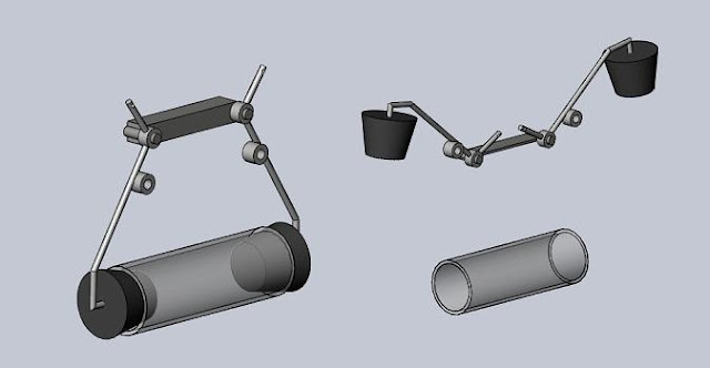
A small gear motor would drive the arms from above, using a crank and rods. A spring joining the arms by their midpoint bushings would maintain constant sealing pressure after the sampler is actuated. Another possibility would be a sampler using two ball bearings valves as pictured below:
 When positioned vertically, gravity would hold the ball bearings in place, resting against o-rings and sealing the sample inside. When positioned horizontally, the bearings would separate from the o-rings, allowing flow through the tube. A gear motor could actuate the sampler by pivoting the tube assembly. I'm imagining old computer mouse roller balls would be ideal ball bearings for this application.
This work is licensed under a Creative Commons Attribution 3.0 Unported License.
Design a device which would autonomously monitor various electrochemical and physical properties of water, saving the time-stamped readings to an SD MMC card. It could be deployed in ponds, lakes, streams, storm sewers, etc, and would provide data which could later be plotted to reveal changes in the water body's characteristics over time. It would also collect and store samples of water upon detection of peaks in sensor readings. The collected samples could later be analyzed to determine the chemical components responsible for the detected peaks.
I believe information on water quality should be public. In situations where water quality is threatened and monitoring is lacking or data is confidential, I see an opportunity to provide an affordable monitoring device any competent DIYer could build and use. Schematics and program code for this project will be released under GPL license, and priority will be placed on selecting affordable components and construction methods.
Possible sensors:
- conductivity - indication of TDS, Salinity
- temperature
- pH - ~ $50 probe to purchase
- oxidation reduction potential (ORP) - ~ $50 probe to purchase
- turbidity - construct with IR LEDs, photodiodes and housing to shield ambient light
- depth - gut a cheap/used fish-finder or use pressure transducer at known minimum depth
- flow - pitot w/ differential pressure transducer
Circuit:
Microcontroller - PIC 18F4550 - up to 13 analog input channels (for sensors)
Battery pack constructed from commonly available Ni-mh cells or SLA battery
SMPS buck converter running PIC and SD Socket at 3.3V
Software:
Use Microchip's C18 C compiler
Use PetitFat small device Fat file system to read and write data to .txt file on SD card http://elm-chan.org/fsw/ff/00index_p.html
Sampling Hardware:
If I can find a cheap source for pyrex tube, I imagine the sampler could be built like this:

A small gear motor would drive the arms from above, using a crank and rods. A spring joining the arms by their midpoint bushings would maintain constant sealing pressure after the sampler is actuated. Another possibility would be a sampler using two ball bearings valves as pictured below:

This work is licensed under a Creative Commons Attribution 3.0 Unported License.
Subscribe to:
Comments (Atom)